In this blog we will go through the procedure of configuring static routing on Cisco devices in GNS3.
Prequires
- Install GNS3
- Import Cisco device image as EtherSwitch and Router. I’m using C3660.
Example 1
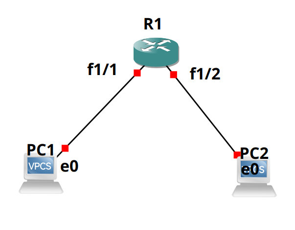
Topology
   fa1/1┌────┐ fa1/2
  ┌─────┤ R1 ├──────┐
  │     └────┘      │
  │e0               │
┌─┴──┐           ┌──┴─┐
│VPC1│           │VPC2│
└────┘           └────┘

Step by Step
on Router:
enable
conf ter
do show interfaces status
interface fa 1/1
no switchport
ip address 192.168.1.254 255.255.255.0
exit
interface fa 1/2
no switchport
ip address 192.168.2.254 255.255.255.0
exit
ip routing
ip route 192.168.1.0 255.255.255.0 FastEthernet1/1
ip route 192.168.2.0 255.255.255.0 FastEthernet1/2
end
on VPC1
ip 192.168.1.1 255.255.255.0 192.168.1.254
show ip
on VPC2
ip 192.168.2.1 255.255.255.0 192.168.2.254
show ip
ping 192.168.1.1
Example 2
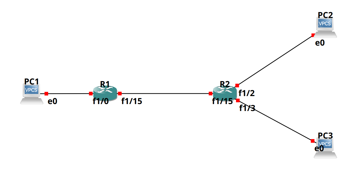
Topology
   ┌───┐                ┌───┐
   │PC1│                │PC2│
   └─┬─┘                └─┬─┘
     │                    │
10.1.3.0/24          10.1.2.0/24
fa1/0│                    │fa1/2
  ┌──┴───┐fa1/15       ┌──┴───┐
  │Route1├─10.1.1.0/24─┤Route2│
  └──────┘       fa1/15└──┬───┘
                          │fa1/3
                     10.1.4.0/24
                          │
                        ┌─┴─┐
                        │PC3│
                        └───┘

Step by Step
on Router1:
enable
conf ter
do show interfaces status
interface fa 1/0
no switchport
ip address 10.1.3.254 255.255.255.0
exit
interface fa 1/15
no switchport
ip address 10.1.1.1 255.255.255.0
exit
ip routing
ip route 10.1.3.0 255.255.255.0 FastEthernet1/0
ip route 10.1.1.0 255.255.255.0 FastEthernet1/15
ip route 10.1.2.0 255.255.255.0 FastEthernet1/15
ip route 10.1.4.0 255.255.255.0 FastEthernet1/15
end
on Router2:
enable
conf ter
do show interfaces status
interface fa 1/2
no switchport
ip address 10.1.2.254 255.255.255.0
exit
interface fa 1/3
no switchport
ip address 10.1.4.254 255.255.255.0
exit
interface fa 1/15
no switchport
ip address 10.1.1.2 255.255.255.0
exit
ip routing
ip route 10.1.2.0 255.255.255.0 FastEthernet1/2
ip route 10.1.4.0 255.255.255.0 FastEthernet1/3
ip route 10.1.1.0 255.255.255.0 FastEthernet1/15
ip route 10.1.3.0 255.255.255.0 FastEthernet1/15
end
on VPC1
ip 10.1.3.1 255.255.255.0 10.1.3.254
on VPC2
ip 10.1.2.1 255.255.255.0 10.1.2.254
on VPC3
ip 10.1.4.1 255.255.255.0 10.1.4.254
Example 3
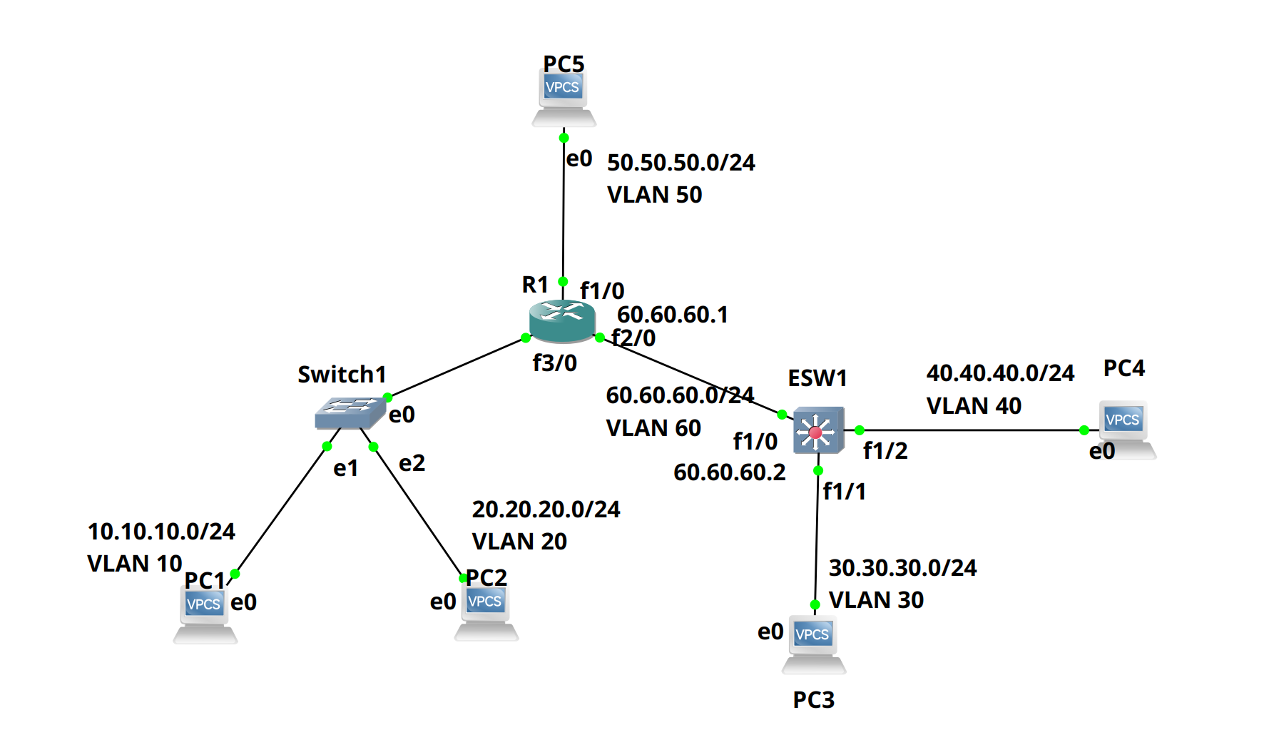
Topology
  10.10.10.10/24   50.50.50.50/24     40.40.40.40/24
    ┌───┐             ┌───┐                ┌───┐
    │PC1│             │PC5│                │PC4│
    └──┬┘             └─┬─┘                └─┬─┘
       │VLAN10          │VLAN50              │VLAN40
  10.10.10.0/24    50.50.50.0/24        40.40.40.0/24
    e1 │                │f1/0                │f1/2
┌──────┴┐e0           ┌─┴┐              f1/0┌┴───┐
│Switch1├─────────────┤R1├───60.60.60.0/24──┤ESW1│
└──────┬┘         f3/0└──┘f2/0  VLAN1       └┬───┘
    e2 │                                     │f1/1
  20.20.20.0/24                         30.30.30.0/24
       │VLAN20                               │VLAN30
    ┌──┴┐                                  ┌─┴─┐
    │PC2│                                  │PC3│
    └───┘                                  └───┘
  20.20.20.20/24                      30.30.30.30/24

Step by Step
on Router1:
Router, Cisco 3660 slot 0: Leopard-2FE slot 1-6: NM-1FE-TX
enable
conf ter

!disable interface 3/0's ip address.
!We're using this interface as a 'trunk' port

interface fa 3/0
no ip address
no shutdown
exit

!set sub interfaces with VLAN

interface fa 3/0.10
encapsulation dot1Q 10
ip address 10.10.10.1 255.255.255.0
exit

interface fa 3/0.20
encapsulation dot1Q 20
ip address 20.20.20.1 255.255.255.0
exit

interface fa 1/0
no shutdown
ip address 50.50.50.1 255.255.255.0
exit


!TODO: SET F2/0 TO COMMUNICATE WITH ESW1

interface f 2/0
ip address 60.60.60.1 255.255.255.0
no shutdown
exit

ip route 30.30.30.0 255.255.255.0 60.60.60.2
ip route 40.40.40.0 255.255.255.0 60.60.60.2

end
on SW1:
L2 Switch, provided by GNS3
Set E0 Trunk dot1Q VLAN 1
set E1 Access VLAN 10
set E2 Access VLAN 20
on ESW1 :
EtherSwitch Router, Cisco 3660 slot 0:Leopard-2FE slot 1:NM-16ESW
enable

vlan database
vlan 30
vlan 40 exit

conf ter
interface f1/1
switchport mode access
switchport access vlan 30
exit

interface f1/2
switchport mode access
switchport access vlan 40
exit

interface vlan 30
ip address 30.30.30.1 255.255.255.0
exit

interface vlan 40
ip address 40.40.40.1 255.255.255.0
exit
ip routing

interface f 1/0
switchport mode trunk
switchport trunk allowed vlan all
exit

interface vlan 1
ip address 60.60.60.2 255.255.255.0
no shutdown
exit

ip route 10.10.10.0 255.255.255.0 60.60.60.1
ip route 20.20.20.0 255.255.255.0 60.60.60.1
ip route 50.50.50.0 255.255.255.0 60.60.60.1

end
on VPC1
ip 10.10.10.10/24 10.10.10.1
on VPC2
ip 20.20.20.20/24 20.20.20.1
on VPC3
ip 30.30.30.30/24 30.30.30.1
on VPC4
ip 40.40.40.40/24 40.40.40.1
on VPC5
ip 50.50.50.50/24 50.50.50.1